Home > Sample Problems > Boeing 747
Boeing 747-200 Aircraft
(Multi-block)
The flow around the Boeing 747-200 aircraft was calculated at cruise conditions using a multi-block grid. The following conditions were used: MˇŢ = 0.855, a = 3.05o, reference area = 5500 sq ft (792,000 sq in), moment center = (1339.91, 0., 191.87) in., moment reference length = 327.8 in., and Re = 10680 per in. The spatial dimensions have been normalized with the moment reference length, leading to a reference Reynolds number, Re = 3.5´106.
Computational
Grid
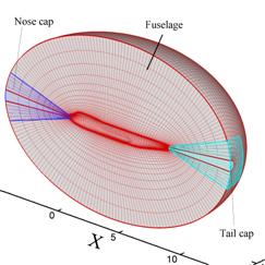
The computational grids contained nine blocks with the following grid points: fuselage 138 ´ 70 ´ 30 = 416,000, nose cone 31 ´ 20 ´ 30 = 18,600, tail cap (31 ´ 20 ´ 30 = 18,600), wing base 129 ´ 38 ´ 30 = 147,060, wing mid section 50 ´ 129 ´ 29 = 187,050, wing tip (top) 77 ´ 41 ´ 28 = 81,508, wing tip (bottom) 77 ´ 41 ´ 28 = 81,508, wing patch 71 ´ 71 ´ 71 = 357,911, and far-field grid 73 ´ 39 ´ 48 = 136,656. This yields a total number of grid points of 1,444,993. The first grid at the wall is located approximately at Dy = 1.0´10-4 which corresponds to a y+ ˇÖ 80. The grid used for the calculations is shown in Fig. 12.1 and described below.
X
(a) (b)
Figure
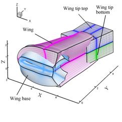
P12.1. Mesh used for the computation of flow around the
B747-200
1. The B747-200
overset grid system
The fuselage surface is modeled using three overset blocks shown in Fig. P12.1(a). Block 2 (fuselage) spans most of the fuselage length in the physical x-direction. Blocks 3 and 4 are designed to cover the nose and tail surfaces of the fuselage. The later blocks are necessary to avert the computational singularities near the two poles.
Figure P12.1(b) shows an ensemble view of the computational grids, Blocks 5 through 8, around the wing. Block 5 (wing base) is a C-H type grid designed to connect the wing and fuselage surfaces. Block 6 (wing) is a C-type grid and extends over most of the wing span. Blocks 7 and 8 (wing tip top and bottom) consist of the H-H topology. The computational blocks around the wing exhibit enhanced grid density near the wing trailing edge and near the wing tip. For all computational blocks near solid walls (Blocks 2 through 8) the normalized grid space value at the wall is D = 1ˇÁ10-4.
A far-field box-shaped grid (not shown in Fig. P12.1) is designed to connect the computational blocks near the fuselage and the wing with far-field conditions. For Block 1, the grids are clustered near the fuselage and wing blocks in all computational directions.
Details of the calculation and some of the difficulties encountered in performing the simulations are presented in a separate paper (Ladeinde et. al., 2006). The results are discussed below.
Figure
P12.2. Early time temporal evolution of the residuals for
high-order
CFD simulation of flow over Boeing 747-200
(a) (b)
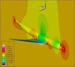
Figure 12.3
Pressure field around the B747:
(a) Entire airplane, (b) Shock compression on the wing
The Spalart-Allmaras turbulence model was used for the viscous calculations. The calculations proceeded without any difficulties and the residuals (Fig. P12.2) indicate convergence. Sample pressure contours are shown in Fig. P12.3. The shock location expected on the surface of the wing can be observed in the plots.
Finally, in Fig. 12.4, we compare WENO and MUSCL results for the Boeing simulation for the same grid. It appears that the WENO results are more physical, and therefore more accurate, although no test problems are available for this case.
Figure
P12.4 Profiles of the pressure coefficient from MUSCL and WENO calculations at
several wing sections of B747-200: (a) y/Lref=0.5, (b) y/Lref=1.0, (c)
y/Lref=1.5, and (d) y/Lref=2.5. Here Lref
is the pitch moment reference length
Obtain
the Files
Setup file (b747.afl)
Grid file (fuselage.grd, nosecap.grd, tailcap.grd, wingbase.grd, wingmid.grd, wingtiptop.grd, wingtipbot.grd, wingpatch.grd and infinity.grd).
References
Ladeinde, F., Alabi, K., Safta, C., Cai, X., Johnson, F.,
2006. ˇ°The First High¨COrder Simulation of Aircraft: Challenges and
Opportunitiesˇ±, AIAA 2006-1526. 44th Aerospace
Sciences Meeting,